
What Is a Transistor? How It Works, Types and Uses
 by
by
A transistor is a semiconductor device that uses a small electrical signal to control a larger current. It works as an electronic switch or as an amplifier, and every processor in your phone or laptop is built from billions of them working together.
Most explanations jump straight into electrons, junctions and equations, and that is where beginners usually get lost. Before going into the physics, I want to ensure the basic idea is clear: a transistor has a control input and a separate current path, and the control input decides how much current that path carries. The physics makes far more sense once you have seen one working circuit, so that is where we start.
How Does a Transistor Work?
A transistor has three main terminals. One of them is the control input, and the other two carry the current being controlled. The names change with the transistor family:
- BJT (bipolar junction transistor): the base is the control input, and current flows between the collector and the emitter.
- MOSFET (metal-oxide-semiconductor field-effect transistor): the gate is the control input, and current flows between the drain and the source. The full device model has a fourth terminal, the body, which most discrete MOSFETs tie to the source inside the package.
The control input works like a valve on a water pipe. A small effort at the valve decides whether a large flow passes, stops or passes partly. The analogy holds for on, off and in between, and it breaks in one place that matters: a BJT’s valve needs a small current flowing into the base to stay open, while a MOSFET’s gate holds its state with almost no steady current.
That control can be used in two ways. In a switching circuit, the transistor sits fully off or fully on. In an amplifier, it sits partly on, so that small changes at the input produce larger changes at the output. Neither behavior involves moving parts. Both come from how charge carriers move through doped silicon.
Example: An NPN Transistor Switching an LED
The quickest way to see a transistor work is a 5 V circuit that turns an LED on and off. The LED and its resistor connect between the 5 V supply and the collector of a small NPN transistor. The emitter goes to ground, and the control signal reaches the base through a second resistor. Designers call this a low-side switch, because the transistor sits between the load and ground.
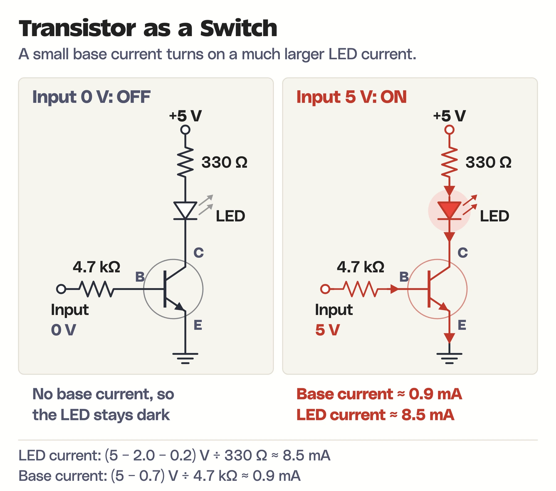
With 0 V at the input, no current flows into the base, so the transistor stays off and the LED stays dark. With 5 V at the input, a small base current flows, the transistor turns fully on and the LED lights. These are the values behind the diagram, for a typical red LED:
- Supply voltage: 5 V
- LED forward voltage: about 2 V
- Transistor voltage drop when fully on: about 0.2 V
- LED resistor: 330 Ω, the nearest common value above the 280 Ω that a 10 mA target needs
- Base resistor: 4.7 kΩ
Ohm’s law gives both currents. The voltage left across the LED resistor is 5 − 2 − 0.2 = 2.8 V, so the LED current is:
$$I_{LED} = \frac{5 – 2 – 0.2}{330} \approx 8.5\ \text{mA}$$
The base sees 5 V minus the 0.7 V base-emitter drop, across 4.7 kΩ, so the base current is about 0.9 mA. That is roughly a tenth of the LED current, which is the usual rule of thumb for driving a small-signal NPN fully on. A 0.9 mA signal is controlling an 8.5 mA load, and the two currents follow different paths.
These values are illustrative. Before you build it, check the transistor’s pinout, current rating and the LED’s datasheet, because pin order differs between parts that look identical.
Types of Transistors
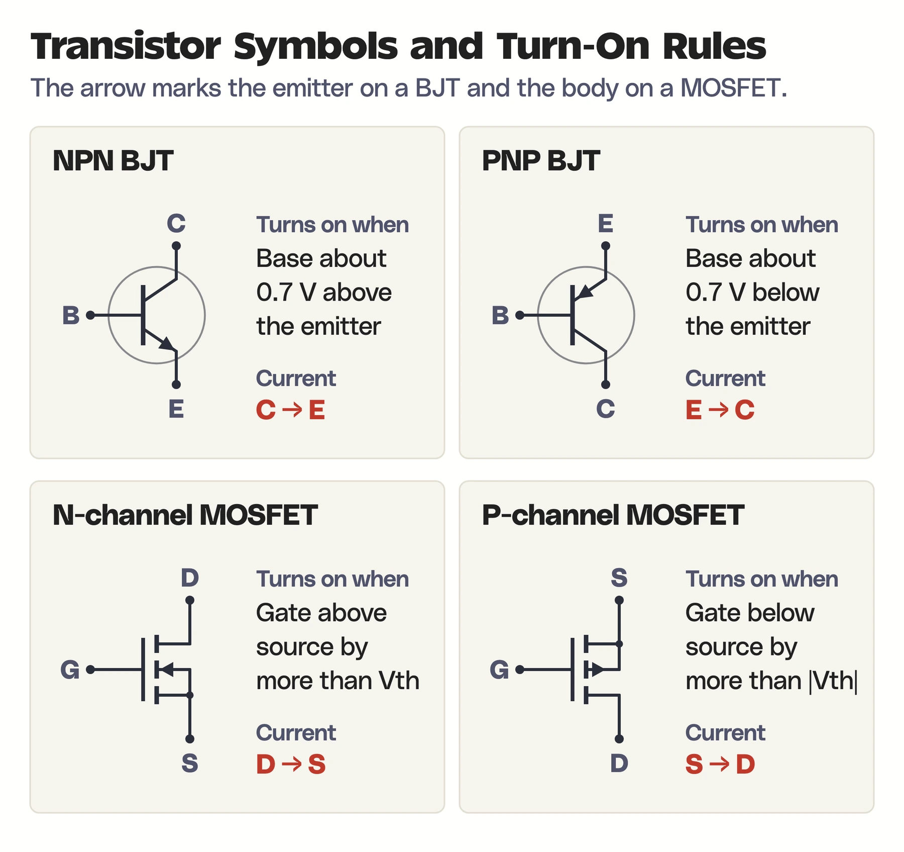
Transistors fall into two big families, grouped by how the control input affects the current path. Bipolar junction transistors use carrier injection across semiconductor junctions. Field-effect transistors use an electric field from the gate. Each family comes in two polarities, which gives the four symbols you will see on almost every schematic.
BJT: NPN and PNP
A BJT has three regions called the emitter, base and collector, stacked as NPN or PNP. The two types are mirror images:
- NPN: turns on when the base is about 0.7 V above the emitter. Conventional current flows from collector to emitter. It is the usual choice for low-side switches like the LED circuit above.
- PNP: turns on when the base is about 0.7 V below the emitter. Current flows from emitter to collector. It is the usual choice for high-side switches, where the transistor sits between the supply and the load.
The arrow on the emitter tells them apart. It points out on an NPN and in on a PNP, in the direction of conventional current. What matters in a real circuit is always the voltage relative to the emitter, never the absolute voltage on the base.
MOSFET: N-Channel and P-Channel
A MOSFET controls current with an electric field from an insulated gate. The two enhancement-mode types, the ones you meet in almost every circuit, are:
- N-channel (NMOS): turns on when the gate is above the source by more than the threshold voltage, Vth. Current flows from drain to source.
- P-channel (PMOS): turns on when the gate is below the source by more than the threshold voltage. Current flows from source to drain.
Depletion-mode MOSFETs, which conduct until the gate turns them off, also exist but are far less common. The junction FET, or JFET, is an older field-effect design that uses a reverse-biased junction instead of an insulated gate.
BJT vs MOSFET
Both families can switch and amplify, but they suit different jobs. This is how they compare in practice:
| Feature | BJT | MOSFET |
|---|---|---|
| How it is controlled | Base-emitter voltage, with base current flowing | Gate-source voltage across an insulated gate |
| Steady input current | Yes, the base draws current while on | Almost none, but each switch charges and discharges the gate |
| Where it shines | Analog amplifiers, RF stages, simple current drivers | Digital logic, power switching, battery devices |
| Main limitation | Current gain varies with current and temperature | Gate charge, leakage and switching losses |
Two other names come up often. An IGBT combines an insulated gate with bipolar conduction and is common in high-voltage power electronics such as motor drives. GaN and SiC are semiconductor materials, gallium nitride and silicon carbide, used to build fast or high-power transistors. They describe what the transistor is made of, which is a different question from its shape, such as FinFET or GAAFET.
How a Transistor Works as an Amplifier
A transistor can also turn a small signal into a larger copy of itself. A microphone signal, for example, is far too weak to drive a speaker directly, and an amplifier stage makes up the difference.
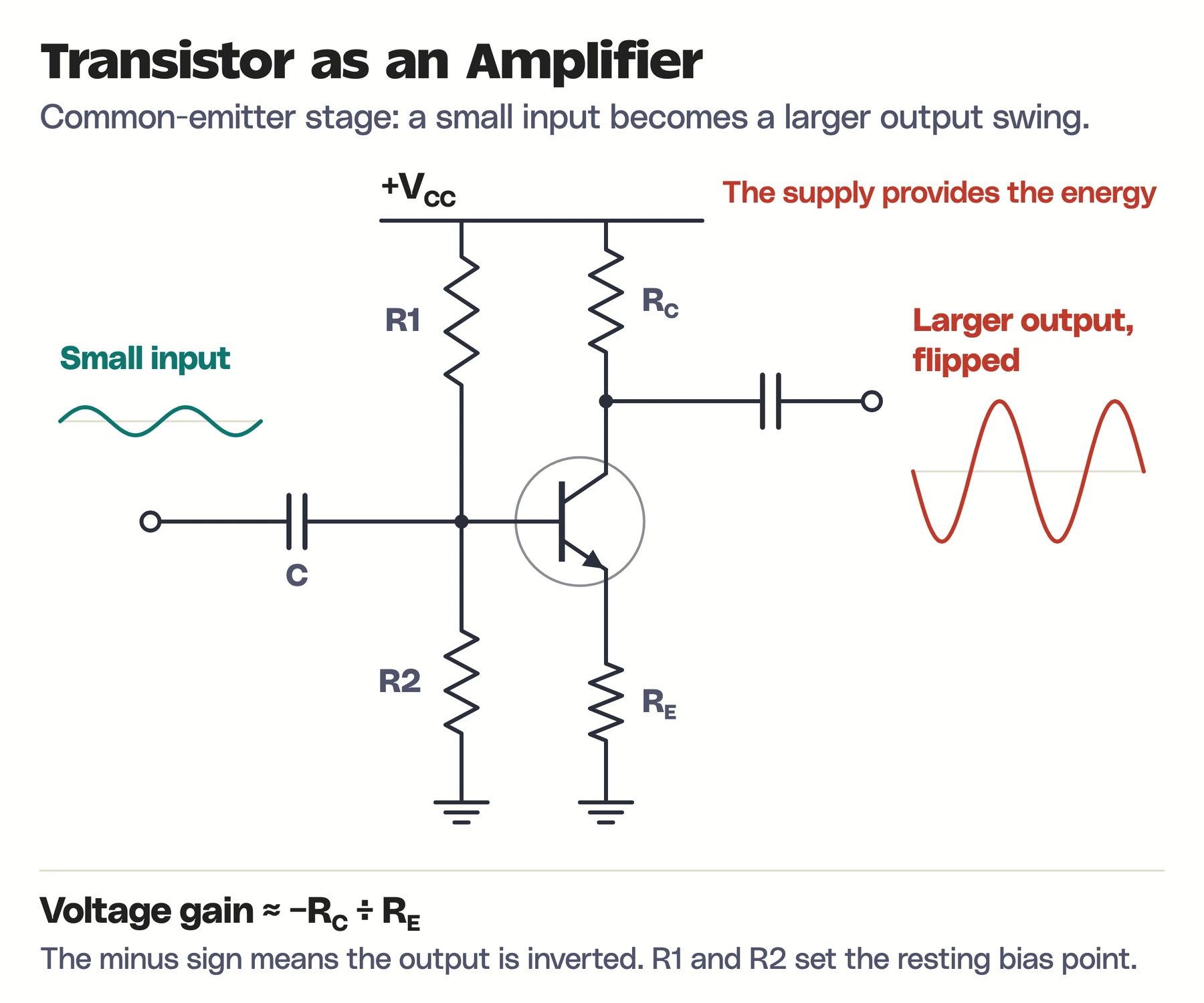
In the common-emitter amplifier above, resistors R1 and R2 hold the transistor partly on, at a resting point between off and fully on. The input signal rides on top of that resting point and nudges the base voltage up and down. Each small nudge produces a much larger change in collector current, and the collector resistor turns that current change into a large voltage swing at the output.
The transistor does not create energy. The supply provides it, and the transistor controls how much of it reaches the output. Two details in the diagram are worth noticing:
- The output is inverted. When the input rises, more collector current flows, the voltage drop across RC grows and the output falls.
- The voltage gain is set mostly by the resistors, about RC ÷ RE, which keeps it steady even though the transistor’s own current gain varies from part to part.
Real amplifier design trades gain against bandwidth, noise, distortion and temperature stability. The resistor values change with the transistor and the job, which is why the diagram shows names rather than numbers.
How MOSFETs and BJTs Work Inside
The circuit view above is enough to use transistors. To understand why they behave this way, and why chip designers keep changing their shape, we need to look at the semiconductor regions themselves.
How a MOSFET Channel Forms
An n-channel MOSFET has two heavily doped n-type regions, the source and the drain, sitting in a p-type body. A thin insulating layer separates the gate from the silicon. With the gate at 0 V, the p-type body sits between source and drain and blocks current.
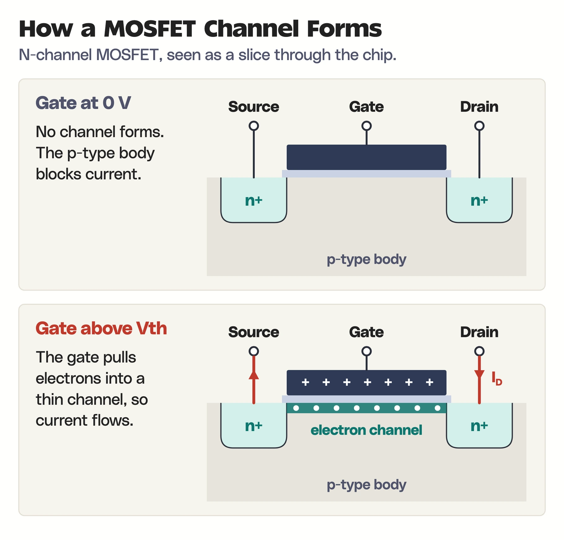
When the gate voltage rises above the threshold, its electric field pulls electrons to the surface under the insulator. Those electrons form a thin n-type layer, called an inversion channel, that connects source to drain. A voltage between drain and source now pushes current through that channel. A higher gate voltage gathers more electrons and allows more current.
For an idealized long-channel NMOS in saturation, a common first approximation for drain current is:
$$I_D \approx \frac{1}{2}\mu_n C_{\mathrm{ox}}\frac{W}{L}(V_{GS}-V_T)^2$$
Here \(\mu_n\) is electron mobility, \(C_{\mathrm{ox}}\) is the gate capacitance per unit area, \(W/L\) is the channel width divided by its length and \(V_T\) is the threshold voltage. The formula assumes \(V_{GS} > V_T\) and \(V_{DS} \geq V_{GS} – V_T\), and it ignores several real effects. It is a teaching model. In a modern nanoscale transistor, velocity saturation, short-channel effects, quantum confinement and leakage all change the current. A power MOSFET used as a switch is analyzed by its on-resistance instead.
These are the parts that matter in the cross-section:
- Source: supplies carriers to the channel.
- Drain: collects carriers from the channel.
- Gate: controls the channel through an electric field.
- Gate insulator: keeps steady gate current tiny.
- Body: the surrounding silicon, which affects the threshold voltage.
How a BJT Moves Current
An NPN transistor has a heavily doped n-type emitter, a thin p-type base and an n-type collector. When the base-emitter junction is forward-biased, the emitter injects electrons into the base. Because the base is thin, most of those electrons cross it before they can recombine, and the reverse-biased collector junction sweeps them into the collector.
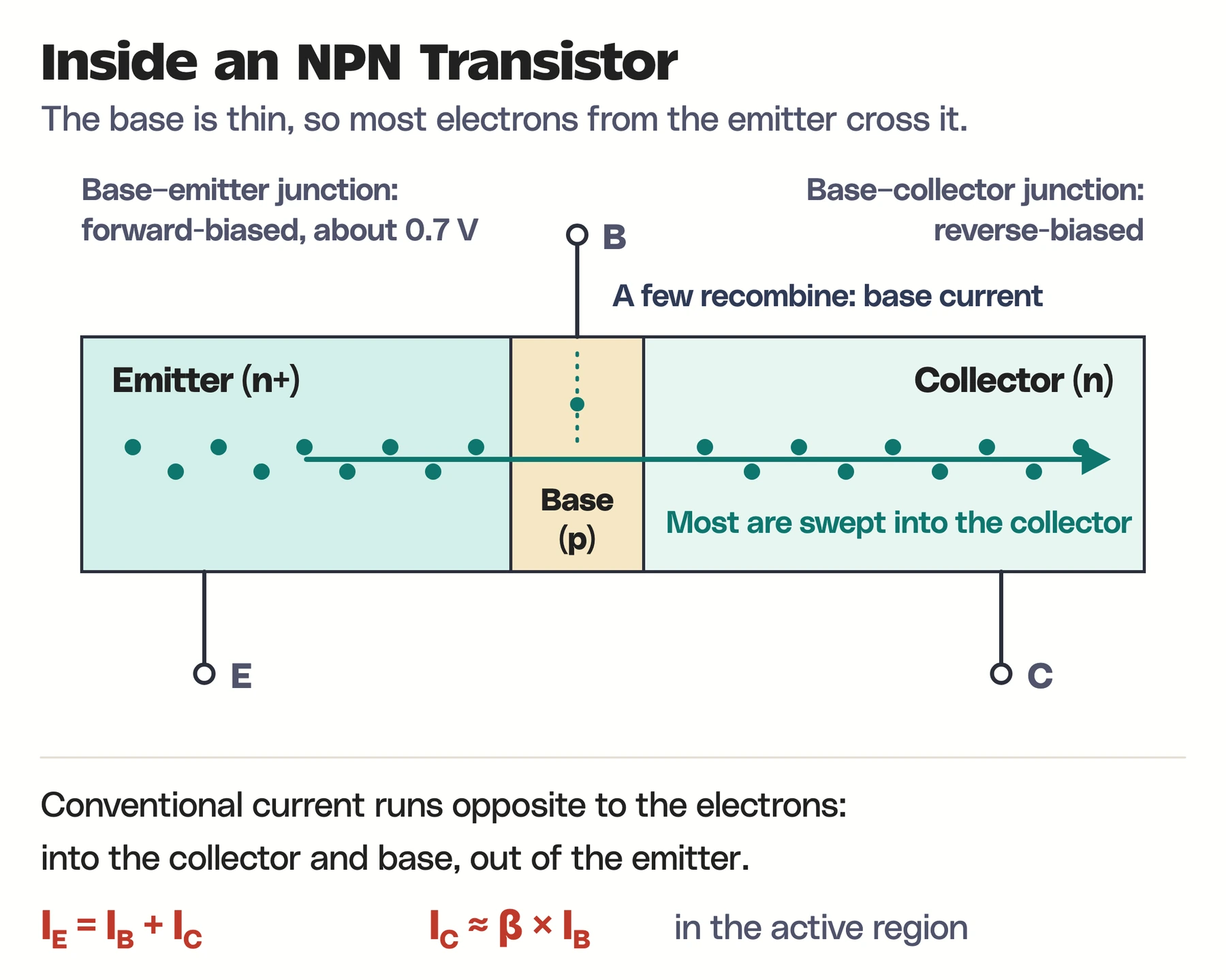
A few electrons do recombine in the base, and replacing them is what the small base current does. The ratio between the two currents gives the familiar simplified relation:
$$I_C \approx \beta I_B$$
The current gain \(\beta\) is not a fixed constant. It changes with the device, the collector current, the voltage and the temperature, and it no longer applies once the transistor is fully on, as in the LED switch. In active operation, the collector current depends more fundamentally on the base-emitter voltage, through an exponential relation:
$$I_C \approx I_S e^{V_{BE}/V_T},\qquad V_T=\frac{k_{\mathrm B}T}{q}$$
The thermal voltage \(V_T\) is about 25.9 mV at 300 K. The Boltzmann constant guide explains the \(k_{\mathrm B}T\) energy scale behind this temperature dependence, and it is the reason a BJT’s current drifts as it warms up.
How Transistors Make Digital Logic
Digital chips use transistors as switches to build logic gates. Almost every modern processor uses CMOS, short for complementary metal-oxide-semiconductor, which pairs n-channel and p-channel MOSFETs so that one of them is always off.
The simplest CMOS circuit is the inverter, or NOT gate. A P-channel MOSFET connects the output to the supply, VDD, and an N-channel MOSFET connects the output to ground. Both gates share the same input.
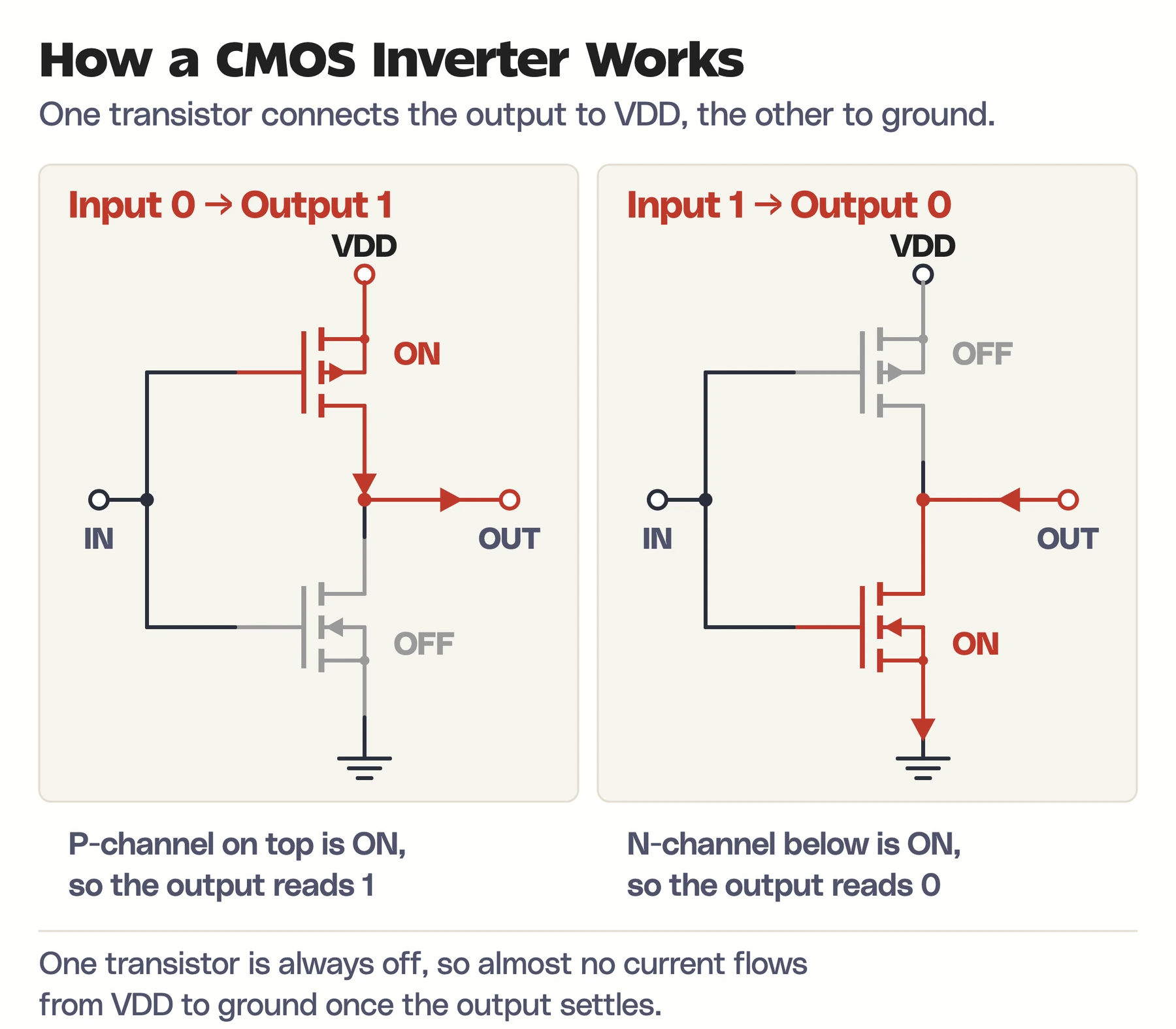
With a 0 at the input, the P-channel device turns on and the N-channel device turns off, so the output connects to VDD and reads 1. With a 1 at the input, the roles swap and the output connects to ground, reading 0. More complex gates such as NAND and NOR use the same idea with more transistors in each network.
Because one transistor in each pair is always off, a settled CMOS gate draws almost no current. Energy is spent mainly when the output switches and charges or discharges the wiring and the gates it drives. The approximate dynamic power is:
$$P_{\mathrm{dynamic}}\approx\alpha C V^2 f$$
Here \(C\) is the switched capacitance, \(V\) the supply voltage, \(f\) the clock frequency and \(\alpha\) the fraction of the circuit switching each cycle. The squared voltage is why lowering the supply voltage has been the most effective way to save power. Leakage and the brief short-circuit current during each switch add to the total, which is why modern chip performance is limited by heat and energy, not only by how many transistors fit.
Applications of Transistors
The same ability to switch and amplify shows up far beyond processors. These are the places you will find transistors doing different jobs:
| Application | What the transistor does |
|---|---|
| CPUs and GPUs | Forms the logic gates and registers that compute |
| Memory | Builds SRAM cells and controls access to DRAM cells |
| Audio equipment | Amplifies weak signals into speaker-level power |
| Phones and radios | Amplifies, mixes and switches high-frequency signals |
| Chargers and power supplies | Switches current on and off thousands of times a second to convert voltage efficiently |
| Motor controllers | Controls current through motor windings |
| Sensors and microcontrollers | Conditions sensor signals and drives outputs |
A designer picks the transistor for the job by load current, voltage rating, switching speed, heat, noise and cost. A tiny logic transistor and a large power MOSFET share a name and a principle, and they are not interchangeable.
Who Invented the Transistor?
John Bardeen and Walter Brattain demonstrated the first transistor, a point-contact device, at Bell Labs in December 1947. William Shockley led the group and developed the junction transistor soon after. The three shared the 1956 Nobel Prize in Physics for that work.
Mohamed Atalla and Dawon Kahng made the first working MOS transistor at Bell Labs in 1959, and the Computer History Museum dates its demonstration to 1960. The MOSFET’s insulated gate and simple flat structure made it easy to shrink and pack densely, which is what eventually made integrated circuits practical.
Transistor Generations
The transistor’s job has stayed the same since 1947, and almost everything else about it has changed: the material, the package, the size and how many fit on one piece of silicon. These are the 5 generations that matter, from a hand-built lab device to processors with hundreds of billions of transistors.
Point-Contact Transistor (1947)
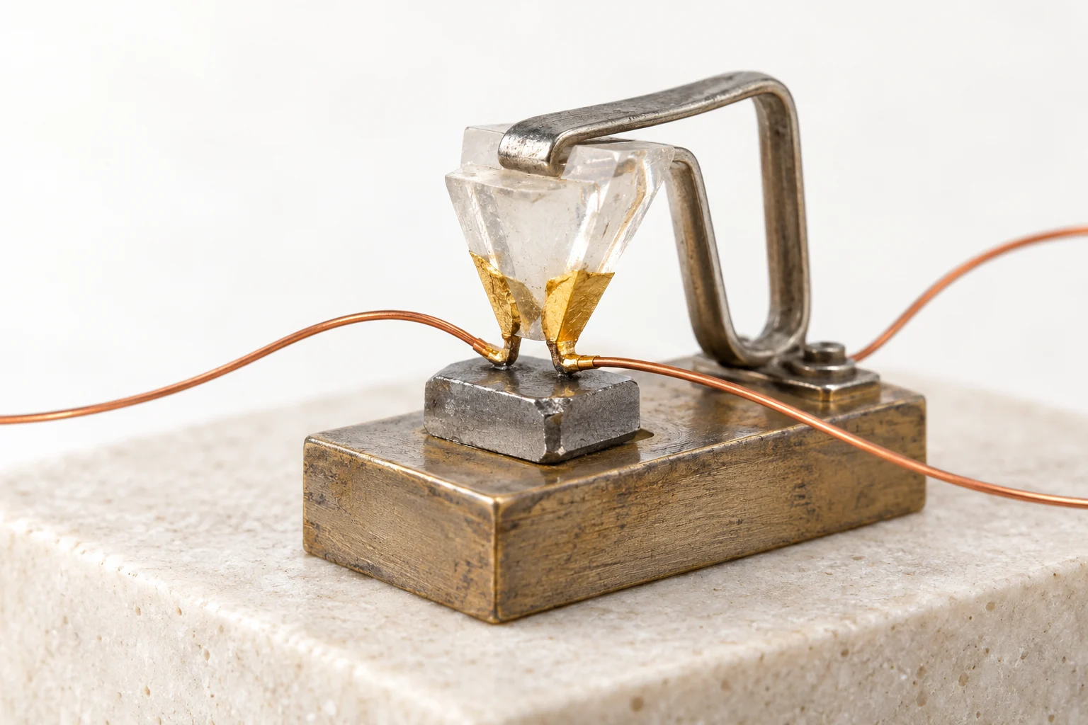
The first transistor, built by John Bardeen and Walter Brattain at Bell Labs in December 1947, pressed two closely spaced gold contacts onto a small slab of germanium. A weak signal at one contact controlled a stronger current at the other, which proved a solid piece of semiconductor could amplify. Its delicate pressed contacts soon gave way to sturdier junction designs.
Germanium Junction Transistor (1950s)
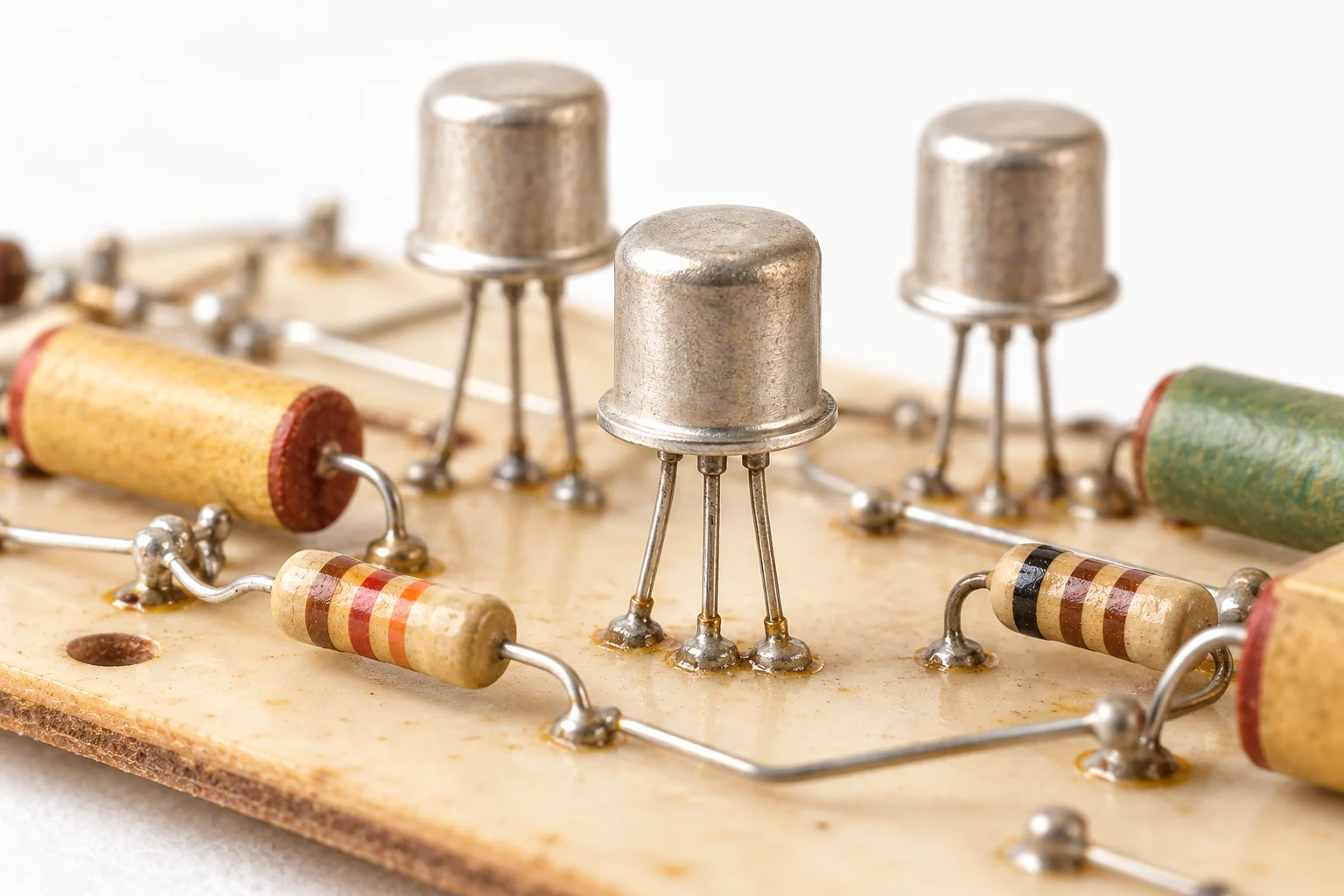
Shockley’s junction transistor moved the action inside a single germanium crystal, with the emitter, base and collector formed as layers. Sealed in small metal cans, these were the first transistors ordinary people bought. They appeared in hearing aids from 1952, and the Regency TR-1, the first transistor radio sold in the US, reached stores in October 1954 with four germanium junction transistors from Texas Instruments.
Silicon Transistor (1954 Onward)
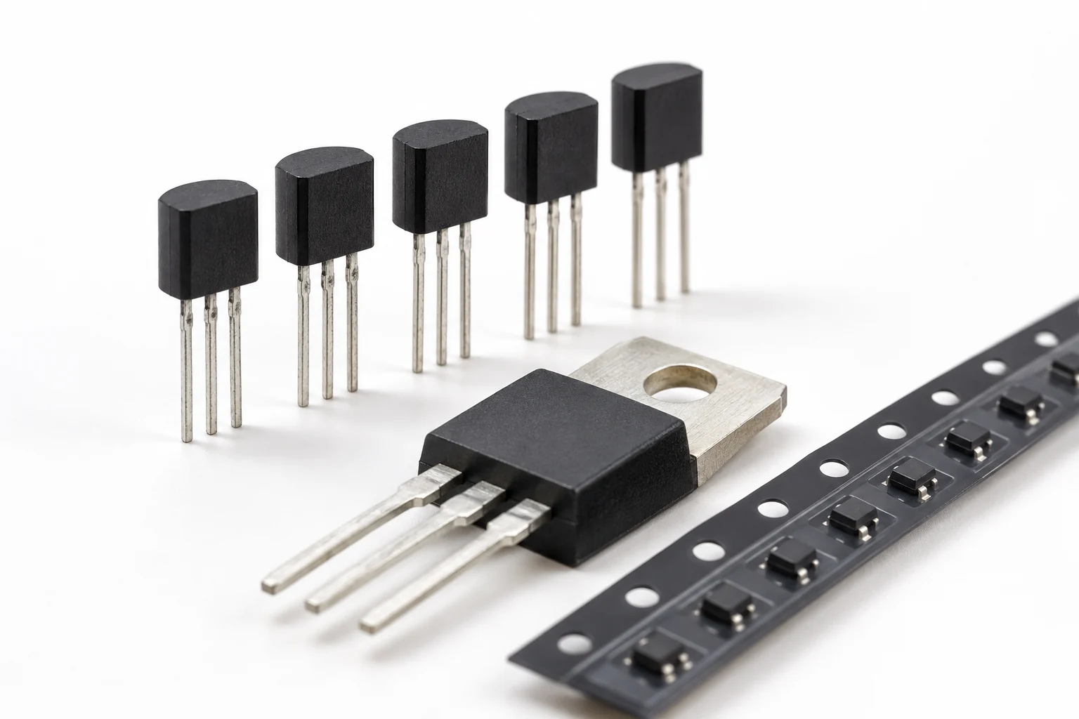
Germanium had two serious problems: it leaked current when switched off, and it only worked reliably between about 0 and 70°C. Morris Tanenbaum made the first silicon transistor at Bell Labs in January 1954, and Texas Instruments sold the first commercial silicon transistors the same year. In 1959, Jean Hoerni’s planar process at Fairchild left a protective oxide layer over the silicon, which made transistors reliable enough for computers. The small plastic and metal-tab transistors on circuit boards today are descendants of that process.
Integrated Circuit (1958 Onward)
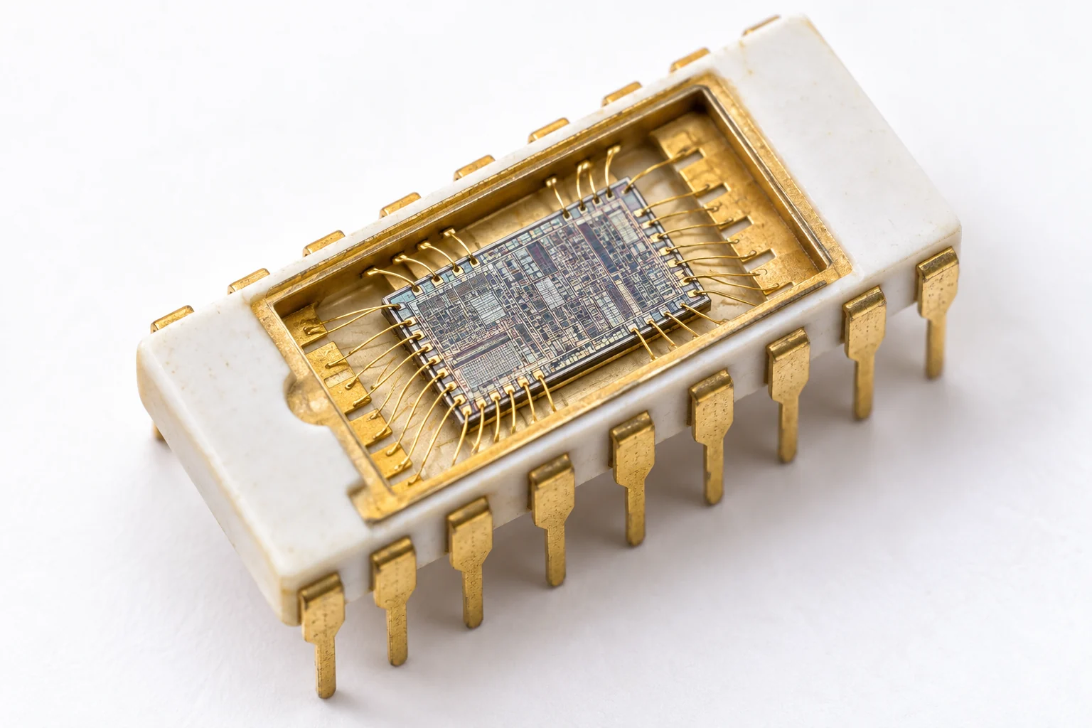
Jack Kilby built the first integrated circuit at Texas Instruments in September 1958, and Robert Noyce at Fairchild patented a practical one-chip design in 1959 using the planar process. Making the transistors and the wires between them on one piece of silicon ended the hand wiring of separate parts. By 1971, the Intel 4004 fit an entire processor, about 2,300 transistors, on a single die.
Modern Multi-Die Processor (FinFET and GAAFET Era)
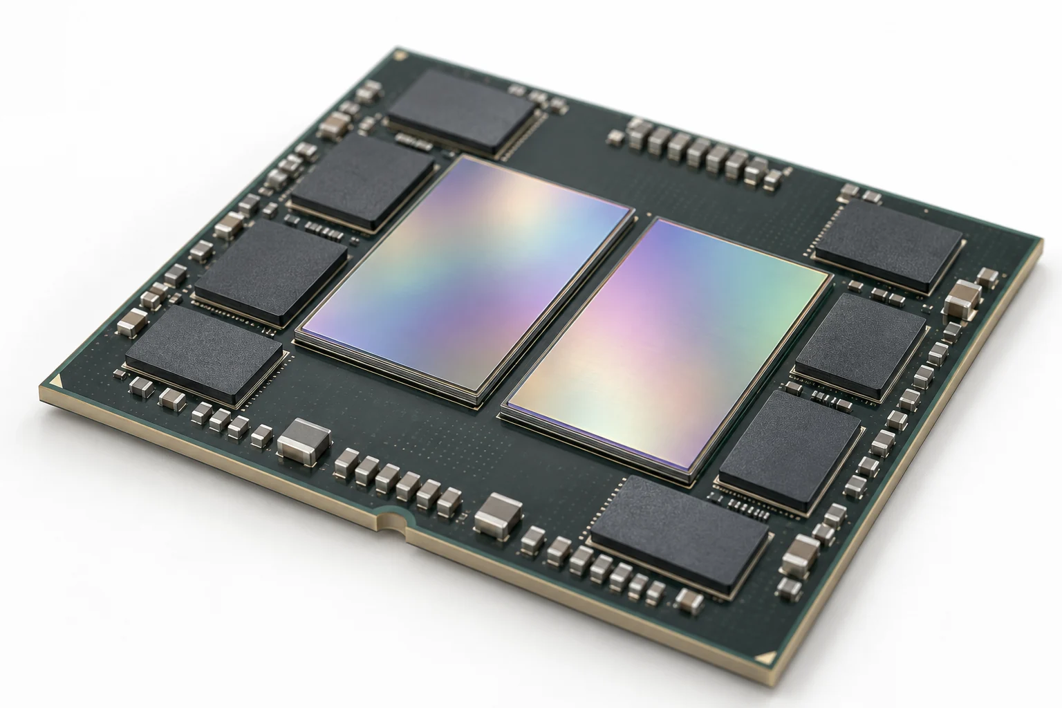
Today’s processors pack billions of FinFET or nanosheet transistors, and the largest designs split them across several dies in one package because a single die can only be made so large. NVIDIA’s Rubin GPU, in full production since early 2026, joins 2 compute dies with 336 billion transistors between them. The transistor shapes inside those dies are the subject of the next section.
Planar, FinFET and GAAFET Transistors
As transistors shrank, the gate found it harder to control the channel, because the drain sits so close that its own electric field starts to leak current through even when the gate says off. Each new transistor shape solves this by wrapping the gate around more of the channel.
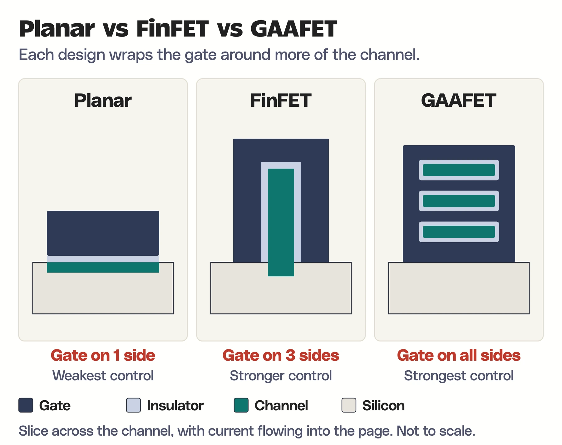
In a planar MOSFET, the gate sits on top of a flat channel and controls it from 1 side. A FinFET raises the channel into a thin vertical fin, so the gate covers 3 sides. A gate-all-around FET, or GAAFET, cuts the channel into thin horizontal sheets and surrounds each one completely. Each step gives the gate stronger control and lower leakage, at the cost of a harder manufacturing process.
| Design | Gate coverage | Why it appeared |
|---|---|---|
| Planar MOSFET | 1 side of a flat channel | The original, simple and scalable CMOS foundation |
| FinFET | 3 sides of a raised fin | Better control as channels shrank |
| GAAFET (nanosheet) | All sides of each stacked sheet | Strongest control, with adjustable channel width |
| CFET (research) | N-channel and P-channel devices stacked vertically | A possible way to shrink logic cells further |
Gate-all-around transistors are now in production. TSMC says its N2 process, its first with nanosheet transistors, started volume production in the fourth quarter of 2025, with the N2P extension scheduled for the second half of 2026. Intel said on June 16, 2026 that Intel 18A, which combines RibbonFET gate-all-around transistors with PowerVia backside power delivery, entered production in 2025. Consumer chips have followed: Apple’s M6 and the A20 Pro in the iPhone 18 Pro, both announced in 2026, are Apple’s first 2 nm chips.
CFET is still a research direction with no announced production date. Imec’s CFET research announcement presents stacked complementary devices as a candidate beyond nanosheets, and the integration challenges are substantial.
What 2 nm and 3 nm Actually Mean
A label such as 3 nm or 2 nm names a manufacturing generation. It is not the length of the transistor or of any single feature on it. Foundries choose their own naming, cell designs, wiring pitches and density targets, so two companies’ “3 nm” processes are not the same thing.
A fair comparison between processes asks about the numbers that actually decide the result:
- transistor density
- performance at a given power
- leakage
- memory density
- yield and cost
How Many Transistors Are in a Modern Chip?
The biggest chips now cross 300 billion transistors. These are the counts the chipmakers have published themselves, newest first:
| Chip | Announced | Transistors |
|---|---|---|
| Apple M6 | August 2026 | Not published |
| AMD Instinct MI455X | July 2026 | 320 billion |
| NVIDIA Rubin GPU | January 2026 | 336 billion, across 2 compute dies |
| Apple M4 | May 2024 | 28 billion |
| NVIDIA Blackwell GPU | March 2024 | 208 billion, across 2 dies |
The Rubin figure is from NVIDIA’s Rubin architecture post, and the MI455X figure is from AMD’s MI455X specifications, which list TSMC’s 2 nm and 3 nm processes. The older counts come from Apple’s M4 announcement and NVIDIA’s Blackwell announcement.
Apple no longer quotes transistor counts for its newest chips. Its M6 announcement calls M6 its first 2 nm chip and says it packs greater transistor density into a smaller die, but it gives no number, and the M5 announcement in October 2025 gave none either. Any M6 transistor count you see online is an outside estimate.
A higher count is not a speed score. Much of any chip is cache, memory interfaces and specialized units, and architecture, clock speed, power limits and software decide how fast it actually runs.
Why Scaling Is Harder Now
Shrinking transistors used to make chips faster, cheaper and more efficient at the same time. That stopped being automatic, for several reasons:
- Gate control: a shorter channel is harder for the gate to switch off cleanly.
- Leakage: thin insulators and tiny gaps let current tunnel through when the transistor is off.
- Wiring: the resistance and capacitance of the tiny wires between transistors can dominate delay and power.
- Variation: a few atoms of difference matter more in a smaller device.
- Heat: more switching in less area raises power density.
- Cost: advanced lithography, masks and fabrication plants keep getting more expensive.
So progress now comes from several layers improving together: new transistor shapes, backside power delivery, better wiring, chiplets, advanced packaging, 3D stacking and specialized accelerators.
Limits and Common Misconceptions
No real transistor behaves like a perfect switch, and a few common beliefs about transistors are wrong in ways that matter:
- Off is not perfectly off. A small leakage current still flows.
- On is not lossless. The on-state voltage drop or resistance turns some energy into heat.
- Switching is not instant. Gates and junctions store charge that has to move before the state changes.
- A transistor does not store a bit by itself. An SRAM cell uses several connected transistors that hold data while powered, and a DRAM cell stores charge in a capacitor that has to be refreshed.
- A MOSFET gate is not free to drive. Its steady current is tiny, but every switch charges and discharges the gate capacitance.
- Silicon is not being replaced wholesale. Silicon CMOS remains the base of computing, while GaN and SiC take over specific power and high-frequency jobs.
Related Physics Guides
If you want the physics behind this article, these guides connect directly to it:
- Ohm’s law, for the resistor math in the LED switch
- Boltzmann constant and thermal energy, for the thermal voltage in a BJT
- Coulomb’s law and electric force, for the field that forms a MOSFET channel
- Physics basics study notes, for the fundamentals
Frequently Asked Questions
What is a transistor in simple terms?
A transistor is an electronic valve made of semiconductor material. A small signal at its control terminal decides how much current flows through its other two terminals, so it can switch a circuit on and off or amplify a signal.
Can a transistor amplify both voltage and current?
Yes. Depending on how it is connected, a transistor can provide voltage gain, current gain or both, which together give power gain. The extra energy always comes from the power supply, not from the transistor.
What is the difference between a transistor and a diode?
A diode has two terminals and lets current flow mainly in one direction. A transistor adds a control terminal that regulates current through the other two, which is what lets it switch and amplify.
Why is silicon used to make transistors?
Silicon is a good semiconductor, it is abundant and it grows a high-quality insulating oxide on its surface. Decades of manufacturing experience also make it the most practical material for chips with billions of transistors.
Why are transistors used in computers?
Transistors act as fast switches that represent 1s and 0s. Connected into logic gates, registers and memory cells, billions of them carry out every calculation a processor performs.
Is a 2 nm transistor actually 2 nanometers long?
No. A 2 nm label names a manufacturing generation, and no single feature of the transistor measures 2 nanometers. Comparing processes needs density, performance and power figures, not node names.
What comes after FinFET?
Gate-all-around nanosheet transistors come next, and they are already in production at TSMC and Intel. Stacked CFET designs, new channel materials and 3D integration are active research directions for the generations after that.
Can I use any NPN transistor to switch an LED?
Most small-signal NPN transistors can switch a single LED, but check the part’s current rating, pinout and base drive against its datasheet first. Larger loads such as motors or LED strips need a transistor rated for that current, and often a MOSFET instead.
Tell Google you want more of this.
Add Gaurav Tiwari as a preferred sourceOne tap, and this site shows up more often in your own Top Stories, AI Overviews and AI Mode. Remove it any time.
Browse more in Physics.